I recently purchased a Panasonic PT-AE700U HDTV projector. One of the features that sold me on the unit is the 12V Trigger output to control an electric screen. This means I also needed an electric screen. I chose the Da-Lite Tensioned Cosmopolitan Electrol knowing that Da-Lite also sells a 12V Video Projector Interface. The plan was to set this all up, plug the projector into the screen and it'll all work wonderfully together. Turns out, not so much.
Getting dirty
I'm a computer hardware engineer. I'm perfectly at home reading schematics and dealing with transistors, voltages, resistances, etc. However, I'll admit to being a bit out of practice when it comes to real-world electronics like relays. I had also assumed that since nobody documented the interface they used for the trigger signal, that it was some sort of standard. So when this didn't all work together I assumed a hardware failure and reached for my multi-meter.
Fortunately, I had tested this with the cables just running along the floor instead of inside the walls. This allowed me easy access to all the components of the system. I measured the output from the projector: 11.4V, that's good enough for me. I tested my cable: end to end continuity, no short between the conductors. "Oh, must be the relay then." So I ran to Radio Shack and picked up a replacement.
Since the replacement was a DPDT relay a friend suggested that I use the other half of the relay to control an outlet. That way, when the projector goes on, the screen will automaticaly come down, and the lamp I plug into that outlet will outomatically turn off. A neat extra feature as a reward for rebuilding the VPI.
At this point I should also point out that the VPI came with a plug-in power cord, and short pigtails for the screen end and the 12V trigger. Not only that, the AC wires were 18 gague, which isn't up to code for being run in a wall. After a trip to Home Depot I came back with a box of 14/2 Romex, a small coil of 14/3, and a spool of in-wall speaker wire for the trigger. Now I could wire.
After a good hard afternoon's work, and lots of help from my girlfriend's father, I had all the wiring done in the walls. It looked sharp. I called everyone into the living room to watch the first working of the screen. I turned on the projector and nothing happened. This was Monday, July 4. At this point, I decided the projector must be faulty, and so I'd call Panasonic the next day.
When 12 volts isn't 12 volts
You won't find it in the documentation anywhere, but the 12V trigger output on the projector is only capable of sourcing 3 milliamperes of current. It took 3 phone trees and two calls to find that out. A quick session using the "Live Help" link on the Da-Lite web site told me that the relay included in the video projector interface draws 88 mA. This is also not documented anywhere. Much frustration would have been saved if both companies had bothered to document that current requirements of their supposedly compatible interfaces.
After doing some googling around, I found a very helpful PDF about using a low-current source to trigger a relay. Exactly my problem! After a bit more thinking and a bit of math (see below), I came up with the following circuit:
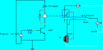
Please excuse my poor Visio skills. I write code and read schematics, I don't normally draw them. I tried to color the wires in the drawing to match the real wire. The orange is a direct solder connection on the little board I made. I also left out the AC ground.
Once I built this and plugged it all in, everything worked wonderfully. I am now very pleased with my projector and screen. I just wish I didn't have to do so much work to get here. If you're planning on using a Panasonic projector with a Da-Lite screen, do not buy the Video Projector Interface for your screen. You'll practically have to rebuild the entire thing anyway.
BTW, I do highly recomend the floating mounting bracket. Also, there isn't much clearence between the back of the screen and the wall. If you want the screen to come down in front of something like a door or window that has molding around it, you'll need to mount the screen on a spacer. I used a 2x4, spray painted black to match the screen's case.
Geeky details
For those of you who want details on how this circuit works, I'll explain it all here.
The replacement relay that I purchased draws 75 mA. The power supply I'm using to provide that current is a spare wall wart that I pulled out of my bin of old computer junk. I think it was for a Caere Typist. Wherever it came from, it's labeled as being able to drive 300 mA. Perfect for my needs.
The transistor is a 2N4401 NPN Switching Transistor. It has a minimum hFE of 100 (according to the back of the package) which means that I need to force 1/100 of the collector current into the base. Since I measured the supply from the projector at 11.4 V and there's a 0.7 V drop across the base of the transistor, I needed to size the resistor to draw at least 0.75 mA from a 10.7 V supply. I doubled that on the advice of the PDF, just to be sure.
So, using Ohm's Law I computed that I needed 7.13 kiloohms. I had 3.3 kΩ and 1.0 kΩ resistors. I used two of the 3.3's and 1 1.0. After connecting them together, I measured with a meter and due to the variations withen the tolerence of the resistors, it totaled 7.4 kΩ. Applying Ohm's Law again told me that would draw 1.44 mA which is comfortably above 0.75 mA, yet still below the projector's limit of 3 mA.
The diode is a 1N4001 Micomini Silicon Diode. I'm not entirely clear on what it's there for, but the PDF said to use one to prevent damage to the transistor, and it only cost $0.59 for a pack of 2, so I figured it was worth it.
Other parts I needed:
And you'll need some random wire and solder, but if you're taking this on I'm going to assume you already have that or at least know how to pick it up.